Autonomous Navigation Robot
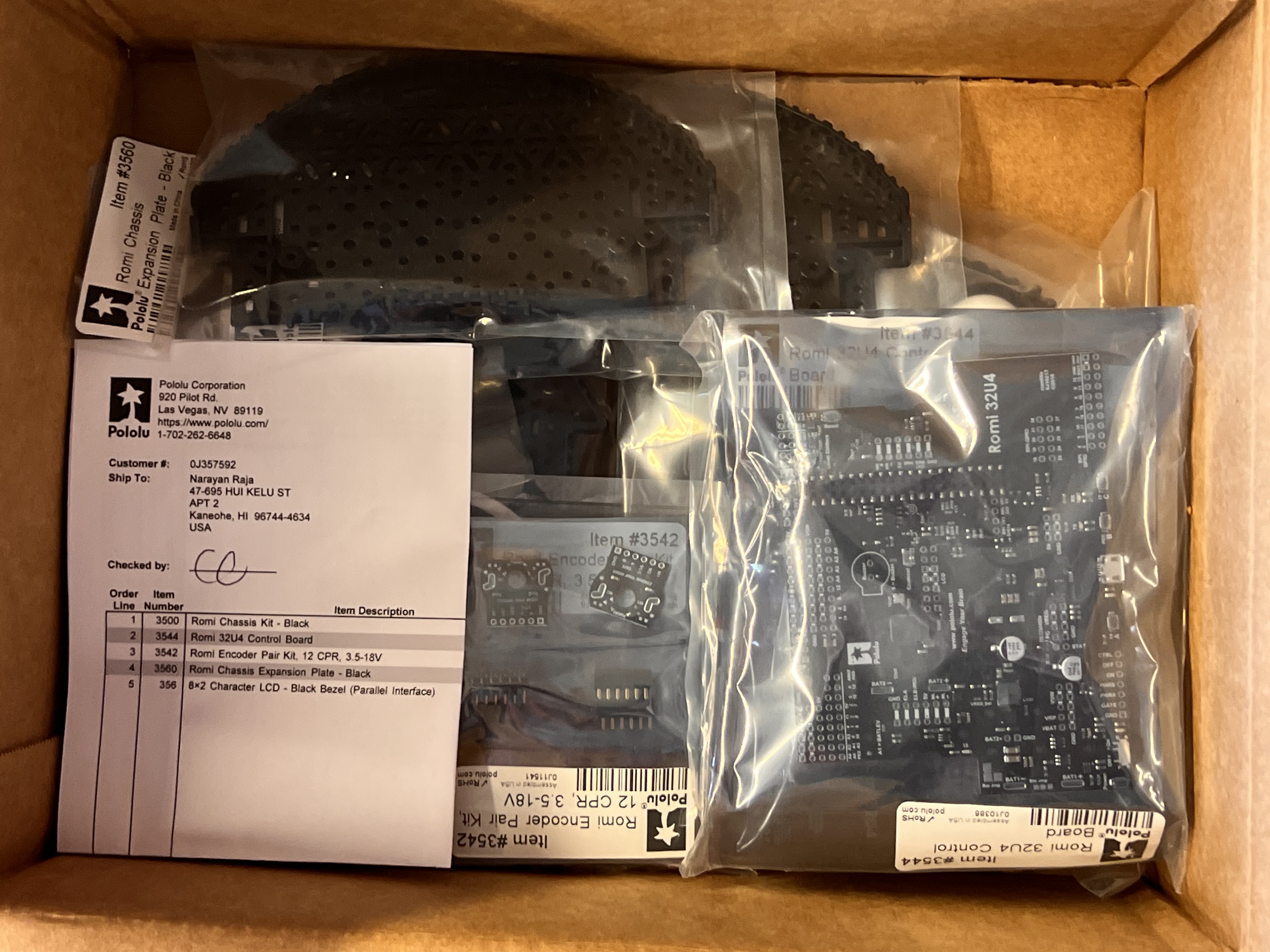
Over the course of the year, I experimented with both kit-based and increasingly customized robot designs, starting from a standard Pololu kit and progressing toward more refined control implementations. I used the Romi 32U4 Control Board and chassis from Pololu as the base platform, which includes built-in quadrature encoders for precise wheel position and velocity feedback.
Because encoder feedback was readily available, I focused first on closed-loop motor control using PID principles. Rather than relying on open-loop motor commands, I implemented proportional–integral–derivative (PID) control to regulate wheel speed and improve trajectory accuracy. This approach allowed the robot to correct for disturbances such as battery voltage changes, surface friction, and minor mechanical asymmetries.
As shown in Figure 2, I began by implementing proportional (P) control, where the motor output is adjusted based on the instantaneous error between the target speed and the measured encoder speed. Proportional control significantly improved responsiveness compared to open-loop control; however, I observed steady-state error when the robot was subjected to sustained load or resistance. This highlighted the limitation of P-only control and motivated further exploration of full PID tuning.
Subsequent experiments incorporated integral and derivative terms to address accumulated error and reduce oscillations. The integral term helped eliminate steady-state bias caused by friction and motor imbalance, while the derivative term dampened rapid changes in error, improving stability during acceleration and deceleration. Through the calibrations shown in Figure 3, I was able to make the robot travel more accurately.
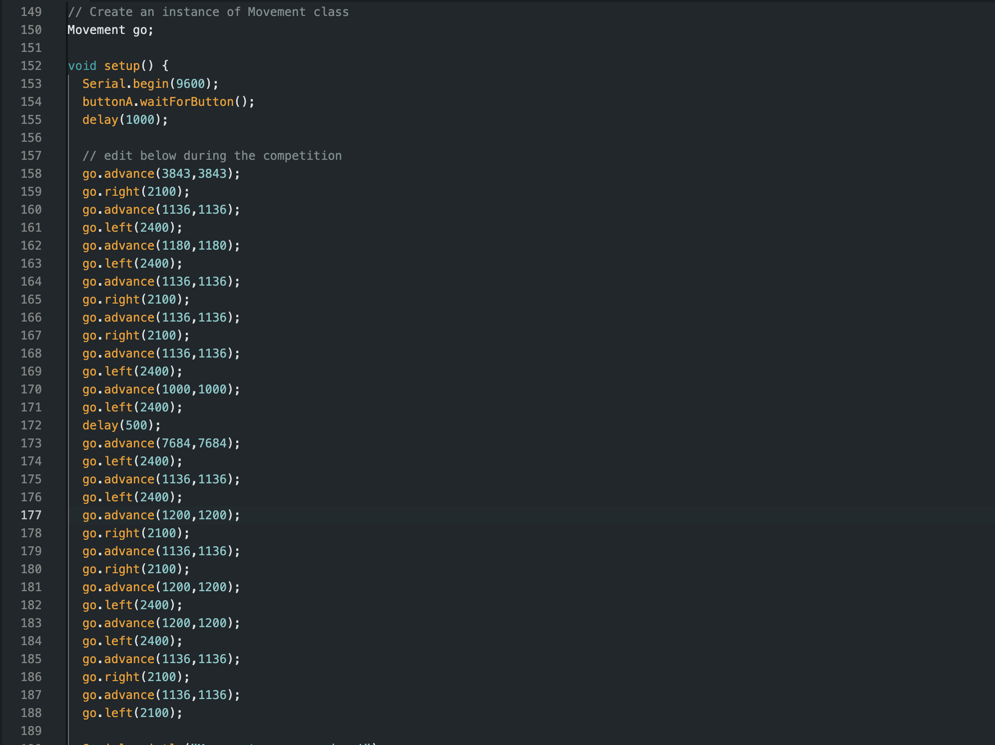
Multiple lines of code were implemented to control the robot’s movements, including forward motion, right turns, and left turns. Each command was carefully programmed to correspond to specific distances and angles, allowing the robot to navigate the square grid accurately. Encoder feedback was used to measure wheel rotations, ensuring precise distance control, while conditional statements adjusted motor speeds to correct deviations in real time.
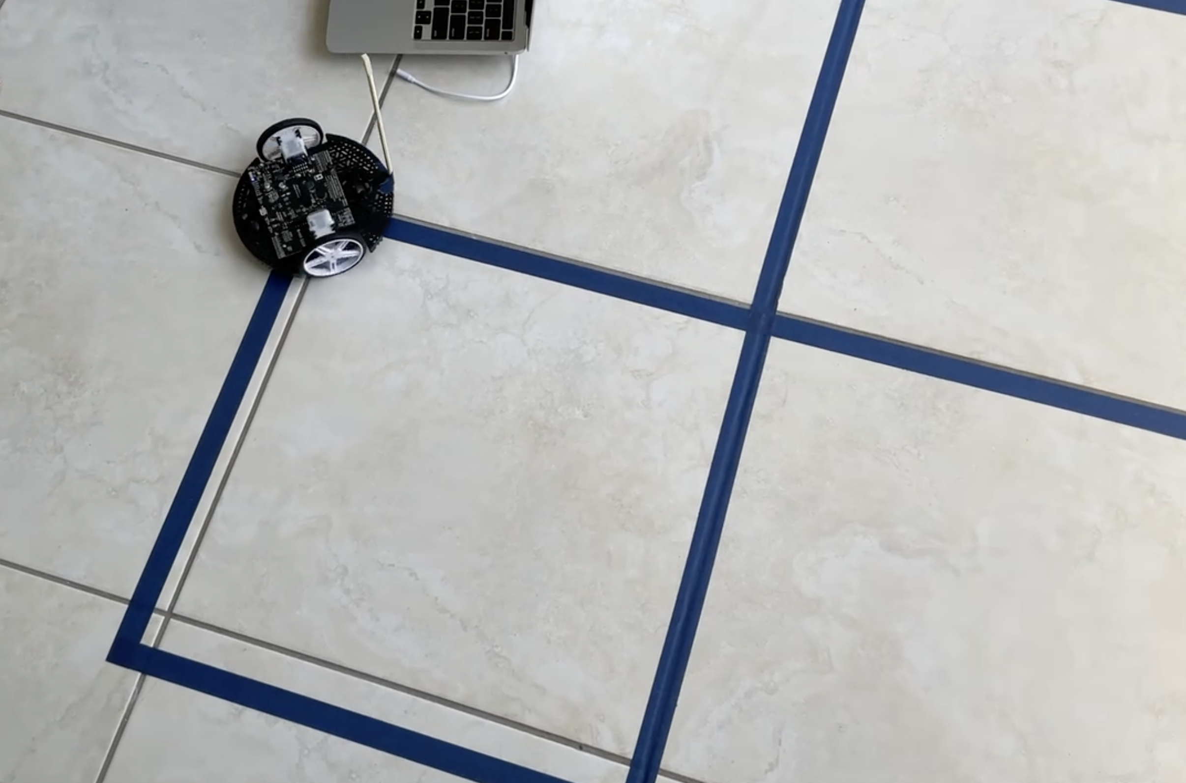
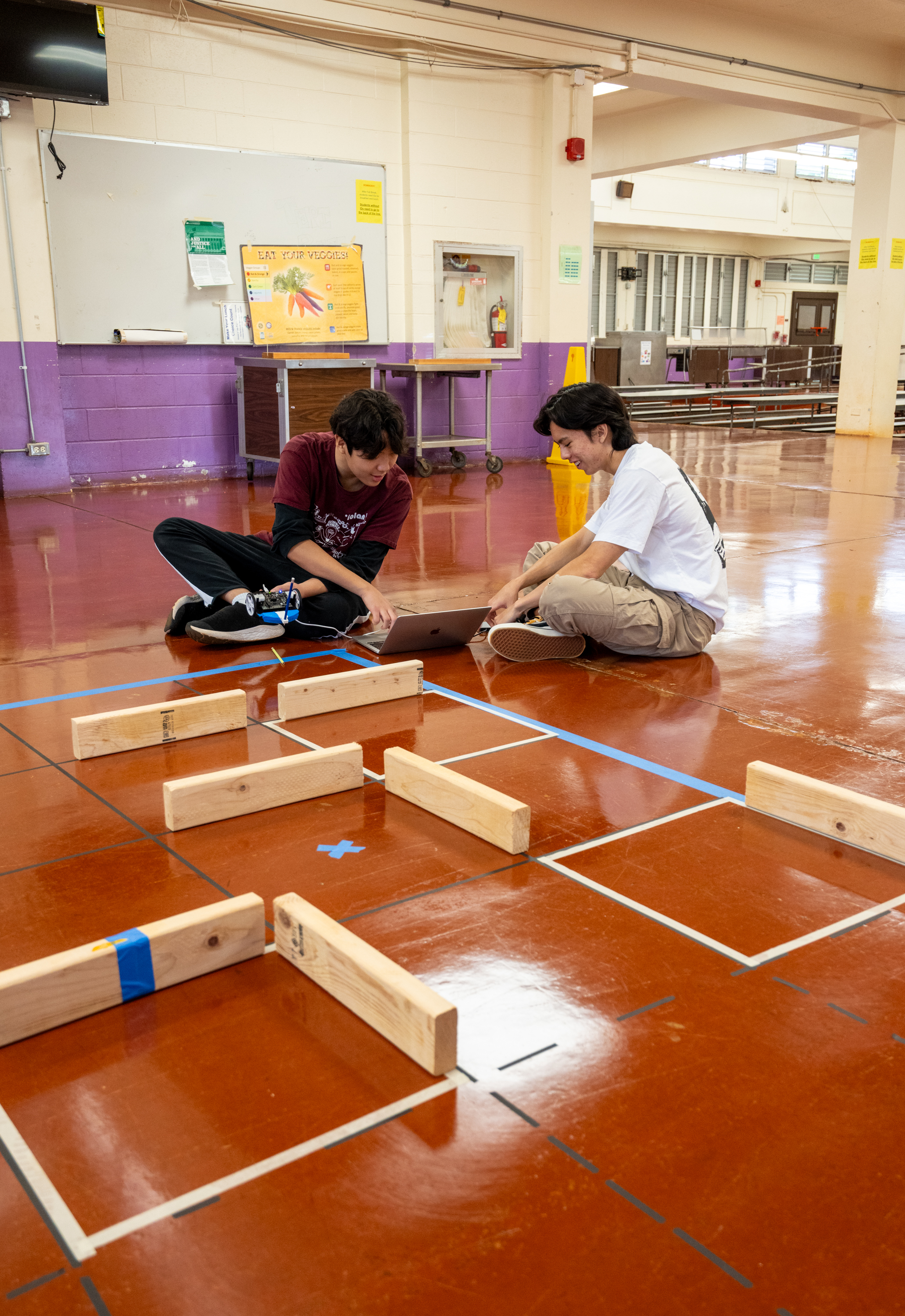
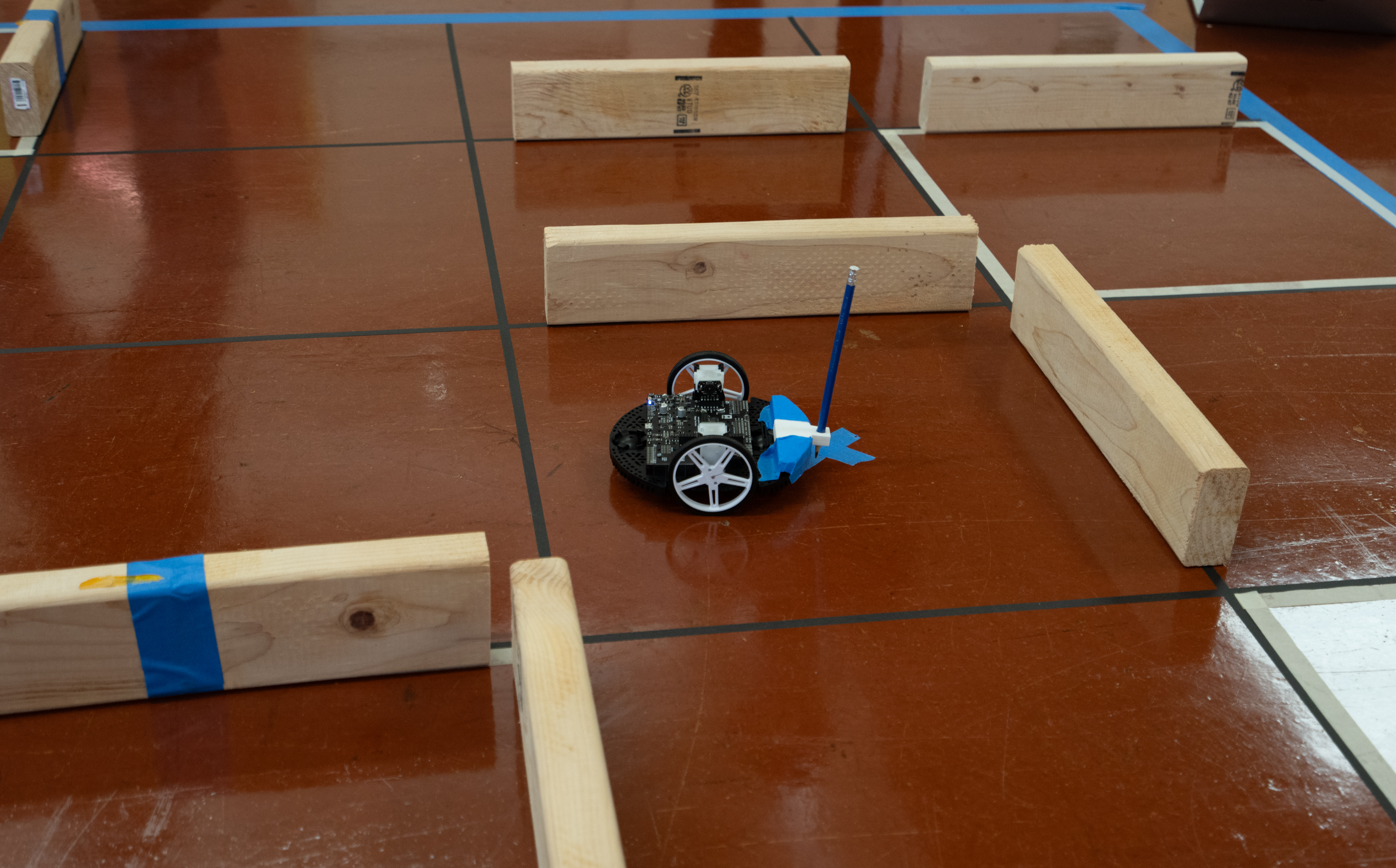
The competition track consists of a 5 × 4 grid of square cells, with each square measuring 50 cm × 50 cm. The robot must navigate from a designated start point to a target location by traveling cell-to-cell across the grid. Please refer to Figure 4 for an example view of the track.
Barriers placed between certain squares act as obstacles, preventing direct movement through blocked paths. These barriers simulate walls, requiring the robot to plan alternate routes and execute precise turns to avoid collisions.
Additionally, there are bonus gates where points are awarded if the robot successfully reaches them. However, there is also a target time, and if the robot significantly exceeds this time limit, a substantial number of points are lost. Therefore, carefully balancing speed and bonus point collection is essential for achieving a high score.
Please refer to Figure 5 for the example lines of code which I actually utilized for the competition run. Each movement lists the encoder count necessary to travel a certain distance. The conversion is:
Nencoder = x · (64 × 50) / (2 π × 4)
| Symbol | Meaning / Value |
|---|---|
| Nencoder | Encoder count (number of ticks recorded) |
| x | Linear distance traveled by the robot (cm) |
| 64 | Encoder counts per motor revolution |
| 50 | Gear ratio (motor revolutions per wheel revolution) |
| 2π | Constant from wheel circumference |
| 4 | Wheel radius (cm) |
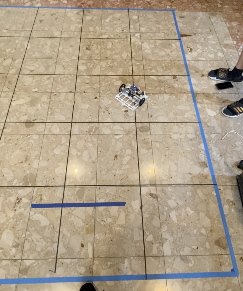
Along with PID control and calibrations, the robot was able to perform very well in many tournaments. The major purpose of the robot is to navigate through the track and reach the target point as closely as possible, as shown in Figure 6.
New Custom Design
Nevertheless, we realized that the quadrature encoders on the Romi kit were not entirely accurate, especially over extended operation. Additionally, the round shape of the Romi made it difficult to align precisely to the track—a critical step to ensure the robot stayed on course.
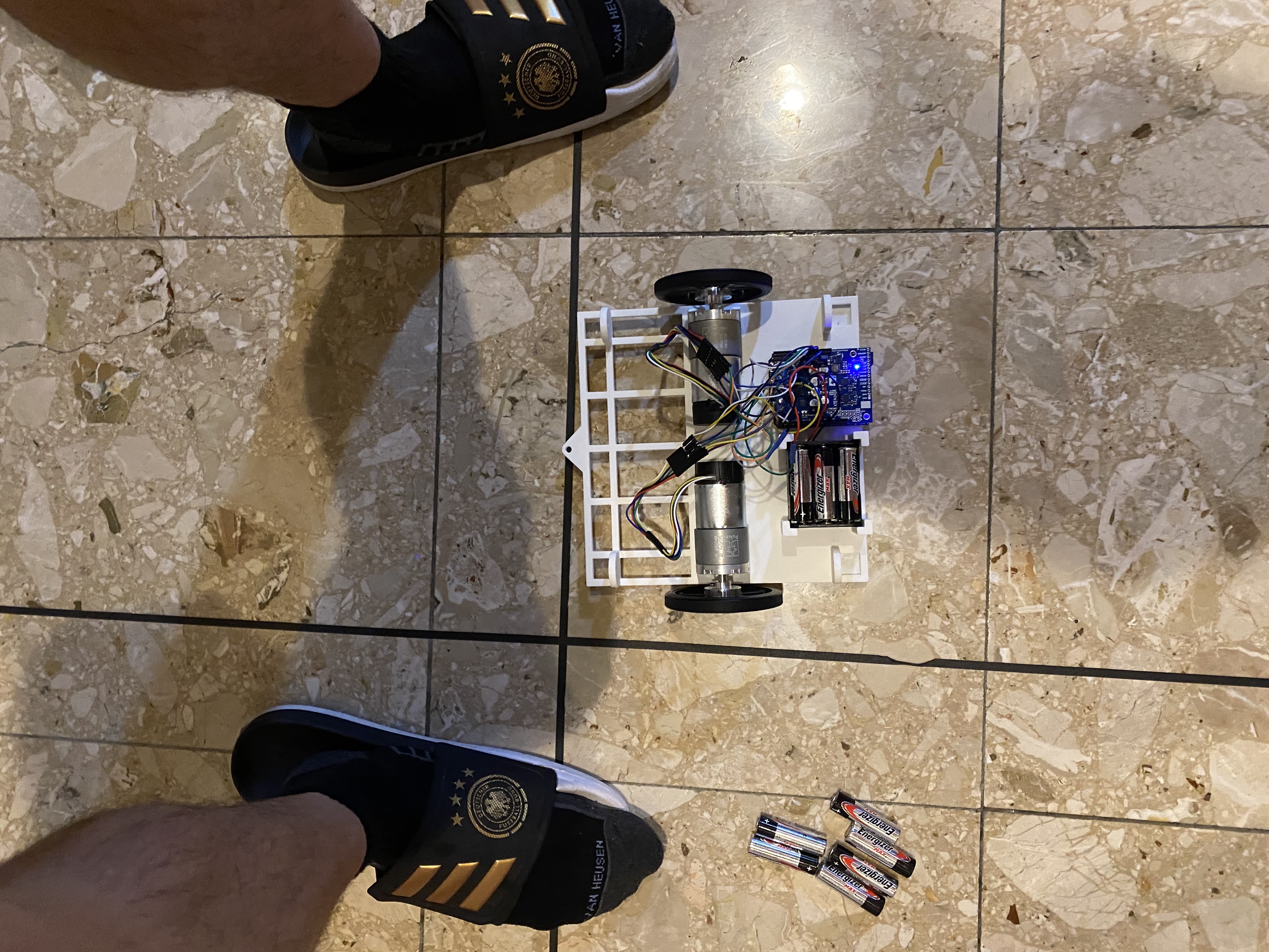
To address these issues, we implemented a custom robot design. The hardware components included:
- Control board: A-Star 32U4 Prime Board with Dual G2 High-Power Motor Driver 18v18 Shield
- Motors: 50:1 Metal Gear Motors (12 V) with 64 CPR encoders
In addition, we designed the chassis to be perfectly rectangular, which made it easier to align the robot accurately to the track. This custom design improved both navigation precision and overall reliability during operation. Please refer to Figure 7 for the design of the robot.
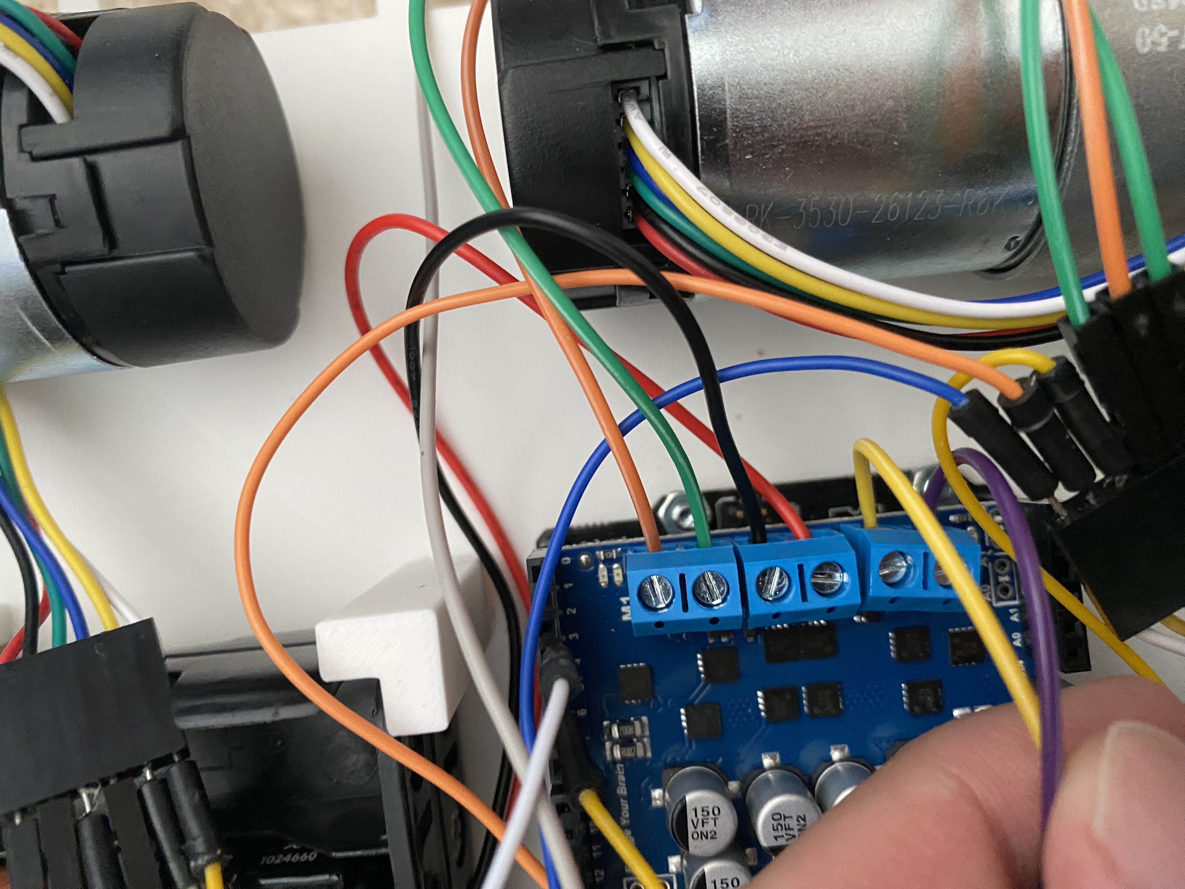
The major modification is the installation of the control board with the motor shield connected to the motors. Please refer to Figure 8 for specific details. The figure shows the black and red wires supplying power to the motor driver, as well as four additional wires, two of which power one of the motors. Each motor also has four wires connected to the encoders.
Other modifications include the implementation of diagonal turns, as shown in Figure 9. Previously, we only employed 90° turns, but with the custom design, we have incorporated 45° turns to minimize the distance the robot must travel.